An evening with the KORG 800 DV schematics
Published: October 10, 2025
What I'm listening to right now (feel free to listen while reading): https://patchingflowers.bandcamp.com/track/pears
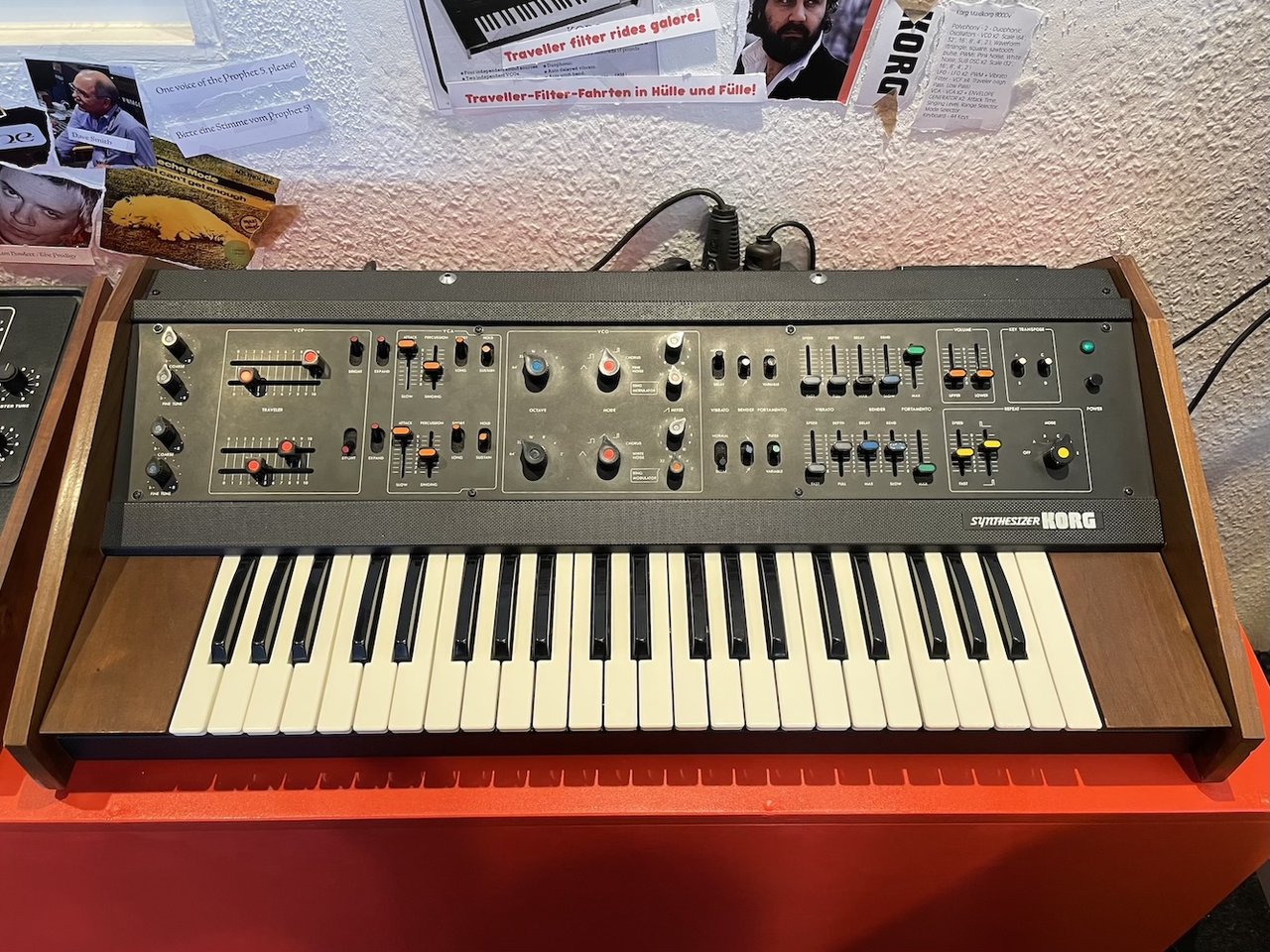
A few months ago, I decided to build a Korg 800 DV from scratch. It's a synth from the 70s and its schematics are available on the web. With the help of some really nice people on modwiggler, I managed to gather even the missing parts of it. Some sections of the circuit have been encased in black boxes. I guess ICs just started being a thing and KORG wanted to ride that train. It does save money to share parts between products and also speeds up development. However, soon chips from other manufacturers where on the market (for much cheaper) which replaced these bespoke circuits. Some of their synths shared these silicone filled plastic boxes that contained core parts of the synthesizers' workings. For example, the 800DV uses the TS200042 VCA, TS201012 Filter and the TS201041 VCO.
All of those secret boxes have been opened by tinkerers over the last 5 decades that the synth existed. This resulted in clean, easy to read schematics for people who needed to fix their synths. They even come with suggested replacements for the transistors that cannot be obtained anymore (since they're out of production).
What could go wrong now? As far as I know, there's one scan of the service manual. Most of it can be read really well but if you dig deeper, you'll encounter missing component values and straight up conflicts between the board layout pages and the circuit diagrams. What might be an even bigger problem: This is my first real electronics project. I soldered before and know my way around components. However, I never designed circuits of any kind so my ability to grasp what's going on just by looking at schematics is limited. So I just start by reading, finding patterns and isolating parts of the circuit that perform particular functions.
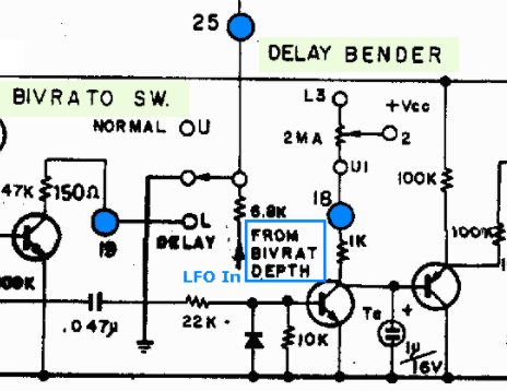
Today I just want to share what I stumbled across. Take a minute to find the nodes labeled with U and L, as well as U1, 2 and L3.
My intuition was that these nodes have to connect to somewhere else. So I searched the circuit diagram and came across the same pattern. One time it was even swapped around (U3, 2, L1). Then it dawned on me: Upper, Middle (2), Lower. These nodes connect to the upper, middle and lower positions of switches and sliders that the user can control.
Depending on how a circuit implements a certain function, either lug 1 or 3 is the upper lug of the switch. Mystery solved! Perhaps it's really obvious but it definitely took me a while to figure out.
- U1: lug number one is up
- U3: lug number three is up
or
- L1: lug number one is at the bottom (lower)
- L3 lug number three is bottom
One weird thing about the 800 DV is: The upper switch positions represent the lower setting while the lower positions represent the higher setting of the parameter. Some potential for confusion if you're used to more recent instruments where up means more.
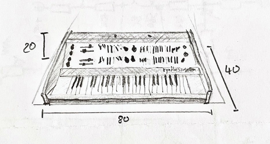
I should definitely write more about this project, I kind of started somewhere in the middle here. It's an interesting synth. This is what it looks like: